Case Study EMI Shield Low Frequency Shielding
OBJECTIVE: To measure the low frequency (below 1 GHz) shielding performance of the XGR Technologies SnapShot EMI Shield and compare it to perforated metal cans.
BACKGROUND: In the article titled “Removable Shielding Technologies for PCBs”, found in the January 2006 issue of Evaluation Engineering magazine, the XGR SnapShot EMI Shield was compared to several PCB-level shielding technologies, with an emphasis on the removable-lid varieties. The data shown in this article was taken using a mode-stirred reverberation chamber that has a lower operating frequency of 1 GHz. There has since been interest in knowing the shielding performance below 1 GHz for this novel PCB-level shielding technology that XGR offers.
THEORY: The basic problem with measuring the performance of a shield at low frequencies is one of dynamic range of the test apparatus. First, whatever radiating device you use for the aggressor, will have poor radiation characteristics at low frequencies due to the size of the radiator being small compared to the wavelength. As a matter of fact, most surface mount components are going to have features that are small compared to a wavelength, and are not going to radiate very much energy at low frequencies. Because of this fact, the tendency is to increase the power level of the source connected to the radiator in order to improve the dynamic range of the test. This presents its own set of problems when dealing with high power sources, including power dissipation into the radiator, general safety concerns, and expense of the equipment. Therefore, you are most likely left with examining data that is close to, if not immersed in, the noise floor of the test system.
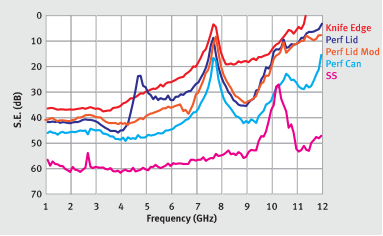
RESULTS: In the article, it was mentioned that an alternative test was performed on the same shields that were tested in the mode-stirred chamber. A “cavity-to-cavity” test was performed that used the same radiating device outside the shield as was used inside. The coupling was measured with and without the shield, and the difference would be the shielding effectiveness of the shield. The data, which was not put into the article because of space constraints, is shown below in Figure 1. The data in this graph actually agrees quite well with the mode-stirred chamber results shown in the article.

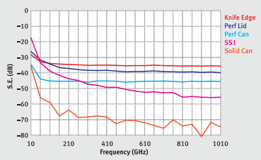
The test equipment used was a medium power source (- +16 dBm) exciting the aggressor under the can and a spectrum analyzer, which was phaselocked to the source, to receive the coupled energy from the receptor outside of the can. Using this setup also allows us to go lower in frequency than the mode-stirred chamber can, with limited dynamic range. Figure 2 shows the shielding effectiveness of the same shields down to 10 MHz.

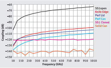
The problem with this data is that it can be misleading as you go lower in frequency, due to the lack of dynamic range. It looks like all of the shielding effectiveness data is trailing upwards, when in fact it is just the radiating device not yielding much radiated energy above the noise floor! To examine this effect, let’s look at the raw coupled data from the results of Figure 2, which are shown in Figure 3.

The “SS1open” trace is the coupling without any shield covering the one radiating device, or aggressor. As you can see, it does not radiate much energy at the low frequencies (which is actually a good thing for the engineer designing the circuit). The “Solid Can” trace provides an idea of where the “noise floor” of this measurement is. All of the shields show good shielding performance all the way down to 10 MHz, and the XGR™ Technologies SnapShot® EMI Shield shows about 120 dB of isolation between the ports of the aggressor and receptor across the whole band.
CONCLUSIONS: It is shown that it is not easy to make EMI shielding measurements at low frequencies, especially for PCB-level shields, where the sizes of the radiating devices are very small compared to the wavelength. The fact that typical surface mount components are very small compared to the wavelength at low frequencies means that they will not produce high levels of electromagnetic radiation or be susceptible to electromagnetic interference. This fact is a good thing for the engineer designing the circuit. However, by examining the raw coupling data in this shielding test fixture, we can discern if the shield is providing an adequate level of additional shielding performance for a particular application. In the test performed above, the XGR Technologies SnapShot EMI Shield provides about 120 dB of isolation between the aggressor and the receptor across the whole frequency band, which is more than adequate for most applications. While EMI is often associated with high-frequency signals, it's equally important to address low-frequency EMI, which can be just as disruptive to sensitive electronic equipment.
REFERENCES “Removable Shielding Technologies for PCBs”, Thomas Clupper, January 2006, Evaluation Engineering magazine

