The demand for compact, dense, and feature-rich electronic devices is increasing every year. These devices feature printed circuit boards (PCBs), which are designed to meet their stringent performance requirements and comply with codes and rules laid by the Federal Communications Commission. The design process of PCB involves consideration of special features, finishing requirements, enclosure design, user interface, and component placement.
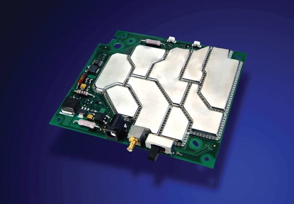
Nowadays, PCB design engineers are also addressing shielding requirements in the design phase. Setting the clearances between the ground and traces, adding grounding in the PCB, and applying conformal spray coating materials are a few common techniques used by PCB designers to minimize the effects of RF and EMI in these PCBs. Sometimes, these shielding techniques may fail to perform; thus, design engineers add metal cans as an additional measure to increase EMC. Metal cans have been in use for a while, still, they have limitations when it comes to repair and maintenance, installation, and conforming to the PCB sizes and shape. This is where thermoformed SnapShot® Board Level Shields can make a difference. This post analyzes how these shields offer design flexibility to PCB design engineers while meeting the stringent requirements of EMI and RF shielding.
How SnapShot® Board Level Shields Help PCB Designers to Achieve PCB Design Flexibility
Today, the size and shape of the PCB is dictated by the design of electronic devices. Sometimes, these boards are irregularly which drives designers to find creative ways of component placement, and fit circuits within standard shapes of traditional metal EMI. However, SnapShot® board level shield makes it quite easy for designers in such situations. How? The following pointers will help you understand it better.
- These shields can be easily thermoformed around the shape of the PCB and circuits to be shielded, enabling design freedom for the designer.
- These EMI shields fit the PCB layout rather than you having to force the design to fit the shape of square and rectangle metal cans.
- XGR Tech can design these shields to suit any of the following:
- Multiple cavities
- Irregular lines
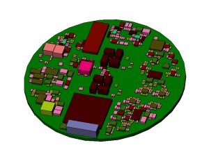
- Radii/circles for round boards
- 3D topography
- Multiple height profiles
- Perforations for heat dissipation
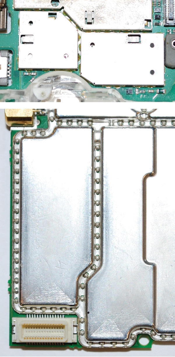
- These shields minimize the space required to shield individual areas. Earlier PCB designers used multiple cans on the PCB to shield multiple circuits. Each can require individual tracing, which is connected to the ground plane. This significantly increases board space required for shielding adjacent circuits. However, the SnapShot® board level shield helps reduce the number of traces. Designers need to use only one trace between adjacent circuits. The single row of solder spheres attached to the ground plane on this trace will completely isolate the two adjacent cavities. See images below comparing adjacent metal cans and multi-cavity SnapShot shields.
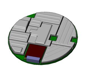
- SnapShot® shields help designers implement all the necessary features, such as entry points for connectors and cables, mouse holes to avoid coupling of RF traces, and air perforations for cooling.
Learn How SnapShot® Board Level Shields Ensure Integration Flexibility and Performance
SnapShot® board-level shields assure integration flexibility and improved performance.
- Integration Flexibility:
When using square or rectangular-shaped metal cans, PCB designers must address space constraints. This is because they must leave sufficient space between the components and the can to avoid shorting. However, with SnapShot® board-level shields, designers needn’t worry about the shorting issues. These thermoformed shields will perfectly conform across boards. They possess a non-conductive surface on the inner side and metalized plastic exterior. This would help reduce the shorting concerns.
In typical scenarios, the can height is often decided based on the height of the tallest component to be shielded. However, the thermoformed shield allows the designer to vary the shield height in a cavity and provides immense flexibility to accommodate enclosure features and surrounding components.
- Performance:
Many engineers use frame-and-lid technologies to shield multiple areas on the PCB. These frame and lid solutions can provide some level of shielding. However, interference may be experienced due to the slot openings between the lid and the frame. These shields have solder spheres, which attach the SnapShot shield to the board both mechanically and electrically. The solder spheres are on 2 mm pitch that connects the shield to the ground plane. These contact points ensure a high level of shielding performance up to 12 GHz. Frame and lid technologies have dimpled contacts, which are typically spaced at least five millimeters apart and do not provide the same high level of shielding effectiveness as SnapShot® board-level shields.
SnapShot shields are made from strong and durable polyetherimide material with a density of 1.27 g/cm3. This material is 80% to 90% more lightweight than steel. The polyetherimide is durable and flexible at the same time.
Conclusion
Shielding components on the PCB is necessary to protect them from EMI and RF. Board designers have incorporated design changes and used metal cans to provide metal shielding. Although these shielding materials assure effective shielding, they impose limitations in terms of size, rigidity, and shape. This is where SnapShot® Board Level Shields help make a difference. They can be thermoformed easily to fit the board shape and allow designers to focus on other areas of design where additional features may be required to meet the user expectations.

